


SOLIDWORKS has many different sketching tools, and learning all of them may be overwhelming. For us to create our first model, the first step should be learning about the essential sketching tools, and I plan to help you with that by writing this post!
First things first: Creating a sketch
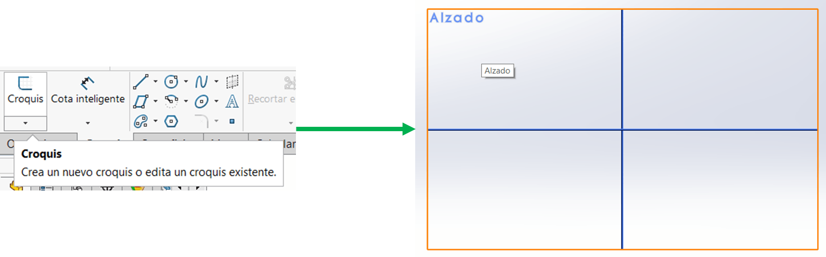
First, we create a sketch to start working in the sketching module. Click on sketch -> sketch -> select the plane to begin your drawing.
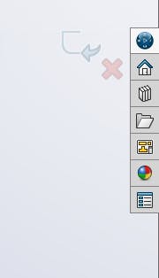
To exit the module, we can click the exit sketch button at the top left or the symbol at the right of the graphical window. If we click on the x, we will discard the changes made on the sketch.
Basic sketching tools
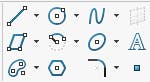
After entering the sketching module, we can see that new options open up in the command bar at the top. Let's check some of those new options.
Basic drawing tools
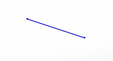
- Line command: You can draw a line by selecting the starting and endpoints. You will keep drawing lines one after the other until you press the Escape key on the keyboard. You can edit any line by moving it around or making it longer.
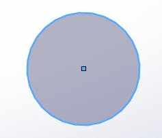
- Circle command: Used to create circles by selecting the centre point and radius.
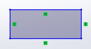
- Rectangle command: You can create rectangles with this tool by selecting two corners of the rectangle.
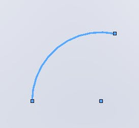
- Center point arc: We can create a portion of a circle by selecting the centre and starting and ending points.
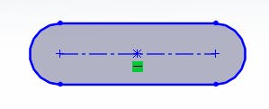
- Straight slot: We can create spaces with rounded sides and straight middle parts.
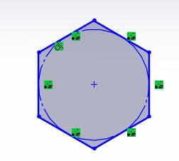
- Polygon: Lastly, we can create polygons of different sides.
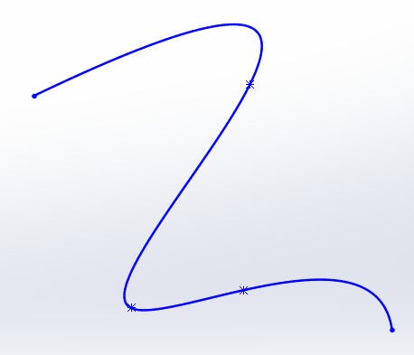
- Spline: We can create smooth curves connecting one to the other.
More tools
We can spot a tiny arrow on each of the commands mentioned above. If we click that arrow, we will see different options for drawing each element. For example, regarding the line command, we can spot the centre line or the midpoint line.
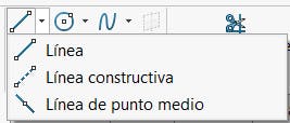
Each of those commands works similar to the first line command. The same happens with the others, such as a circle or arc.
Basic editing tools
Let's check some tools we use to edit previously created geometry:

Sketch fillet: We use this to create rounded corners between two lines or arcs.
Sketch chamfer: Works like the fillet, but to make chamfers.
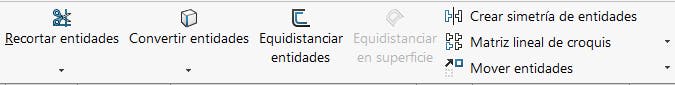
Trim entities: We can use this tool to delete certain parts of the geometry we don't need. For example, lines that intersect between them.
Extend entities: We can see this option if we click on the arrow below small entities. We use this tool to extend the length of our geometries.
Deleting elements
To delete a geometry, we select it and press the delete key on our keyboard. We can delete many different geometries by selecting and dragging with our mouse to create a rectangle to choose everything we want to eliminate and then pressing delete.
To sum up
After this summary of the essential SOLIDWORKS sketching tools, you should be able to start playing around. The best way to improve mechanical design is by practising, so try creating different geometries and getting to know all these useful features better.
Useful links
If you want to know more about SOLIDWORKS, check out the 3D design series!